Flow Cytometry for Oyster (Crassostrea virginica) Hemolymph
Last Revised: 20220324 SJ Gurr
About experiment:
(insert link to the google drive presentation)
Goals:
About probes of interest:
-
JC-10: mitochondrial membrane potential is a key parameter of mitochondrial function and a putative indicator of cell death and general cellular status. Membrane potential is the gradient of protons within the inner mitochondrial space and the mitochondrial matrix where OXPHOS proteins/complexes function in generating this gradient through redox reactions. ATP synthase (complex IV) relies on this gradient, moving H+ ions across the inner space to the matrix to create ATP. Thus high potential is representative of normal/optimal mitochondrial status - Low potential is dubbed as mitochondrial dysfunction
- add here…
- add here…
- add here…
SOPs:
(insert link(s) to our master google drive SOP(s))
C6 Plus manual (BD Biosciences; link here https://www.bdbiosciences.com/content/dam/bdb/marketing-documents/BD-Accuri-C6-Plus-Users-Guide.pdf)
Experimental design/timeline
(insert photos of the trial)
-
chemistry
-
note: the mass flow controller for the ‘high’ treatment was bumped to 7.0, good to note for future efforts but is merely a snapshot due top the temperature, season, ambient conditions, etc.
| Carbonate chem | pCO2 (uatm) | pH | TA | other |
|---|---|---|---|---|
| Low | Elevated | Low | TA here | other |
| High | Ambient | Ambient | TA here | other |
Analysis of flow cytometry data:
| Steps | Flow Cy Probes | |—-|—–| | I | SYBR Green + potassium iodide | | II | JC-10 | | III | add here… | | IV | add here… |
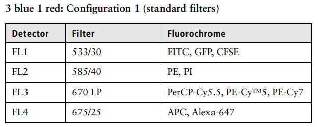
Figure of flourochromes from the C6 Plus manual (BD Biosciences; like above in ‘SOPs’)
I.) SYBR Green + potassium iodide
I.A.) Initial look with SSC vc FSC
-
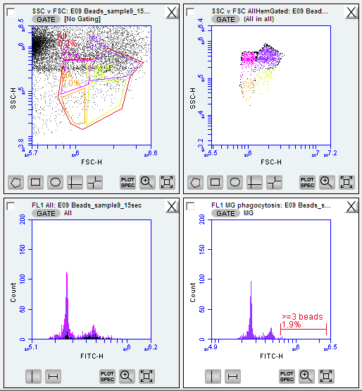
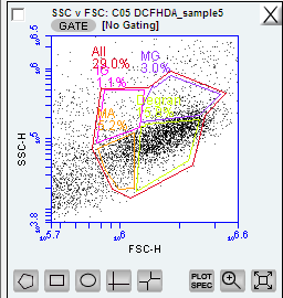
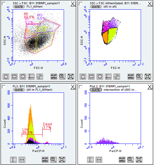
forward scatter and side scatter with SYBR green is an ideal first step when analyzing hemolymph quality and initial gating of your template - these paremeters represent the size of the particles (forward scatter) and their complexity (side scatter)
- NOTE! the initial scatterplot view of your flow cytometry data (assuming no threshold(s) set) will be a messy cloud of noise.
-
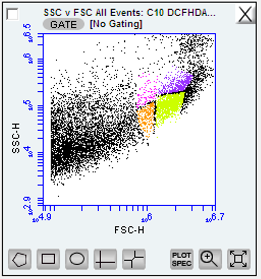
zoom into the tail end of the x axis (in this case forward scatter ‘FSC-H’) and you should see an upward curl of the data in the y axis. This is the region of your hemocytes around 10^5.8 - 10^6.7 on forward scatter log scale
Figure below: raw data on side and forward scatter ignore the color-coded regions as this will initially be all one color at this stage
I.B.) gate with FL1
-
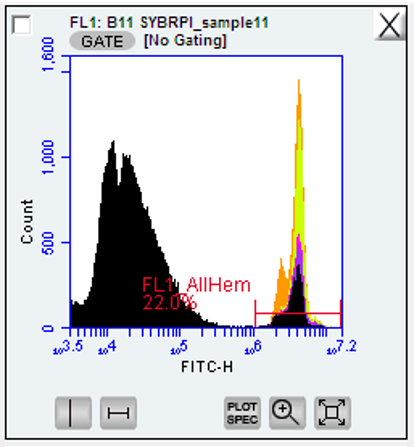
SYBR green binds to DNA and flouresces in the FL1 (533/30) between 10^6 and 10^7
-
create a gate calling the distinct peak wihtin this region
Figure below: SYBR green + potassium iodide after 1 hr 14 minute incubation of oyster hemocytes. Gated region titled ‘FL1’_Allhem’. ignore the color-coded regions as this will initially be all one color at this stage
I.C.) Overlay FL1 gate to SSC vc FSC, gate cell types
-
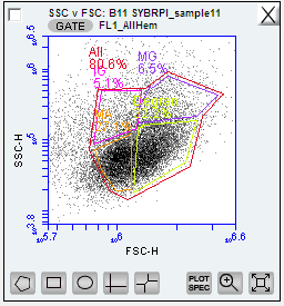
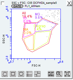
view your SSC vc FSC for all your individuals overlaid with the gated FL1 region, you should now see distinct ‘clouds’ or groupings of datapoints. These are all cells with fouresced DNA (from FL1) and you can now determine cell types!
- NOTE! review your species of interest as taxa differ in the number of parsable hemocyte types
Figure below: SSC vc FSC plot gated for the FL1 - four new gates created and color coded for cell types:
-
IG = immanture granolocytes
-
MG = mature
-
MA = mature granulocytes
-
Degran = degranulated cells
-
All = all hemocytes, gated around the entire area after the four cell types/regations were determines
I.D.) Live vs. dead using FL3
- call the live and dead regions in FL3 - PerCP-H
II.) JC-10
II.B.) About
View JC-10 on FL1 and FL2 to measure the intensity ratio at these wavelengths.
JC-10 selective enters mitochondria depending on the membrane potential, in normal cells/status JC-10 diffuses into the the mitochondrial matrix, whereas in apoptotic/dysfunctional cells JC-10 diffuses out to a monometric form
On FL1… JC-10 monomers, representative of mitochondrial dysfunction/pre apoptotic signatures
On FL2.. JC-10 is concentrated in the matrix forming red fluorescent aggregates.
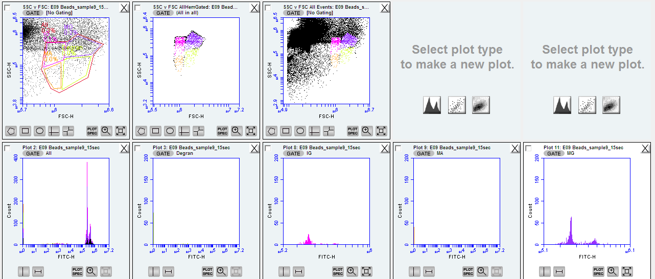
Figure below: Flourescence of JC-10 at the FL1 and FL2 (top and bottom, respectively) parsed by cell type

Where do we go from here?
Time to calculate an arbitrary unit (A.U.)! (odd, but its what we do!)
The value we want here is the relative fluorescence intensity of the FL2 to the FL1 - simply divide the signals to get your A.U.
What does this tell you?
-
high FL2:FL1 (relative to other samples/treatments): represents fewer apoptotic signatures / markers of mitochondrial dysfunction. The mitochondrial contain a higher membrane potential
-
low FL2:FL1 (relative to other samples/treatments): indicates poor cellular status, mitochondrial recycling/apoptosis are likely mechanisms occurring in this sampl, at least at a higher rate and cost than those with higher FL2:FL1
II.B.) Some results!
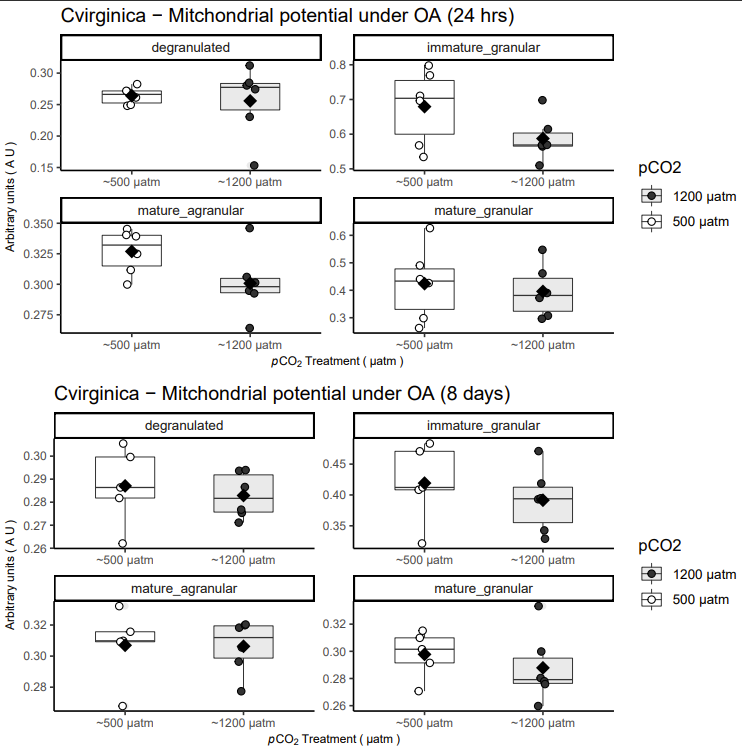
Figure below: Results of JC-10 for adult oysters after 24 hours of exposure to ambient vs. elevated pCO2 (top) and 8 days of exposure (bottom). Panels are parsed by cell type gated wihtin individual with SBYR green
Interpretation of data…
Immature granular and mature agranular cells are affected by elevated pCO2 resulting in lower membrane potential (marginal effect pCO2 at 24 hours; P < 0.1). This difference dissipates after prolonged exposure to elevated pCO2 (8 days).
What could be this mean?
Mitochondrial dysfunction could be the result of elevated pCO2 overloading the bicarbonate buffer in the mitochondrial matrix - resulting in proton leak and decreased OXPHOS efficiently (low membrane potential)
Where to go from here?
Additional flow cytometry probes can further investigate whether this interpretation holds its weight in salt. DCFH-DA detects free radicals in the cell. Dysfunction mitochondria are both the cause and result of excess ROS-induced apoptosis. This is a great direction for for biologically relevant sanity check for this data.
Further, mRNA or qPCR can investigate either the transcriptome profile or a posteriori genes of interested connected with transcriptomic remediation of stress associated with dysfunction. Gene expression is a great snapshot of cellular status although both labor and time intensive to get a result - as opposed to this fact flow cytometric phenotype we obtained here!
III.) DCFH-DA
some notes…
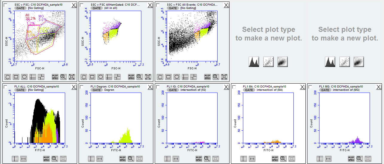
- remove the gate for the FL1 that was made with the SYBR green
- diffueses into cell - hydrolyzes trapped in cell - then oxidizes to DCF by oxided to DCF by ROS and then flouresces
- geometric mean - calculated population flourescence?
- do we want to normalize by live cells within sample/cell type
- mean flourescence intensity - what does this mean? An arbitrary unit? flourecence intensity increases logarithmically - mean is skeweed accurate cannot be estimated due to log scale - geometric mean is teh fourescence intensity of the population
Figure dump… drag and drop to above where needed as you edit..

